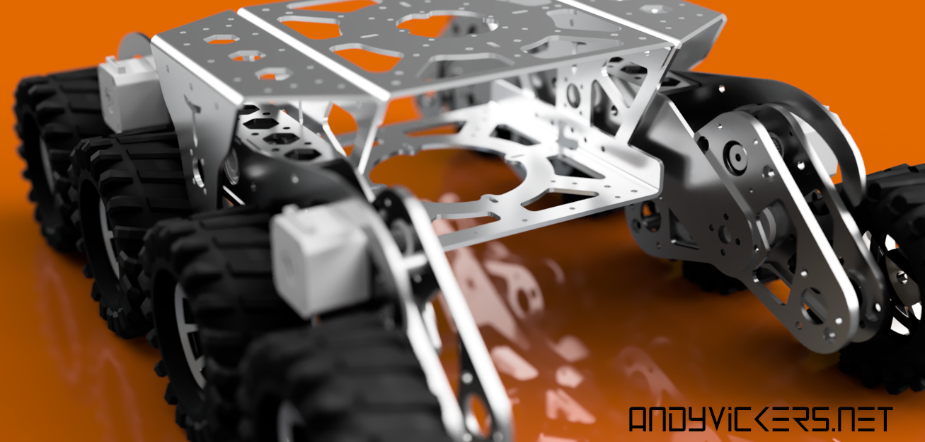
Its high time my suspension and my wheels got connected to a chassis . We need a place to house all the electronics and general payload of the robot . I used Fusion360 to put together some rough designs that used 2020 extrusions and milled plates to build a chassis.
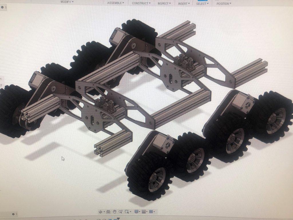
The basic layout so far looks like this, with plates I am going to mill on the Shapeoko and then I will connect these plates with the extrusions. The suspension will mount to the middle sections with some 3d printed components.
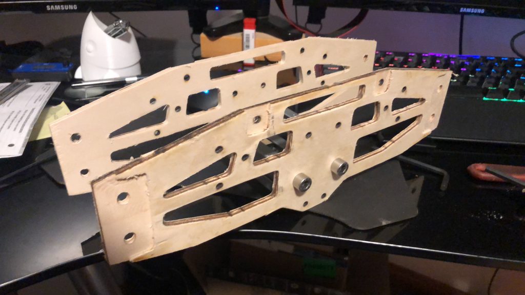
I did not loke the finish on these plates, but I think it was more the wood I was using and the fact I used an upcut endmill than the machine’s fault. In hindsight a down cut would have been better. There is a good post here that explains the difference: How To Choose Solid Carbide Spiral Router Bits | Infinity Cutting Tools Blog (infinitytools.com)
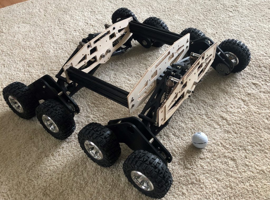
At this point a few things are starting to glare me in the face:
- this robot is wider than it is tall (doesn’t look cool)
- it has ground clearance challenges because the suspension protrudes lower than the hubs
- the plates don’t attach well to the extrusions, and there is a lot of flex
This badly shot video shows how well it scales over objects:
Not willing to stop doing a bad design to death I wanted to at least get some forward motion happening and try and learn all I could from this platform. I added back the steppers so I could try moving the robot
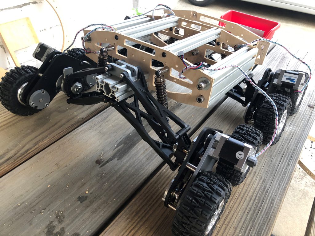
Here’s a look at the underside
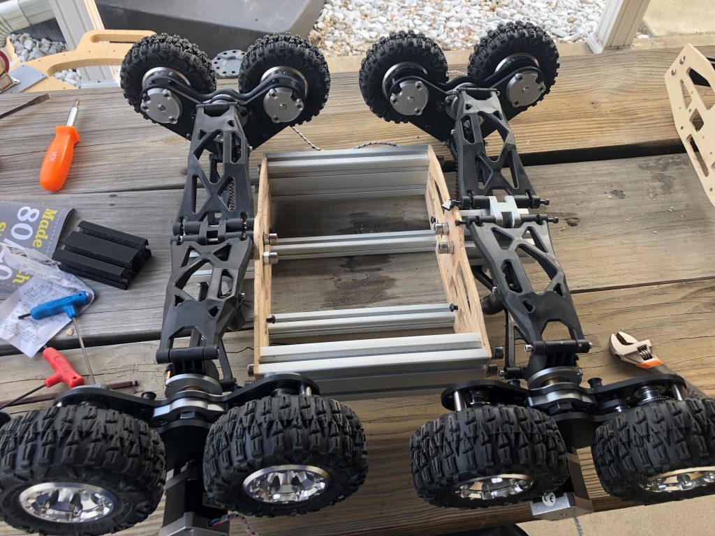
and here’s a side profile
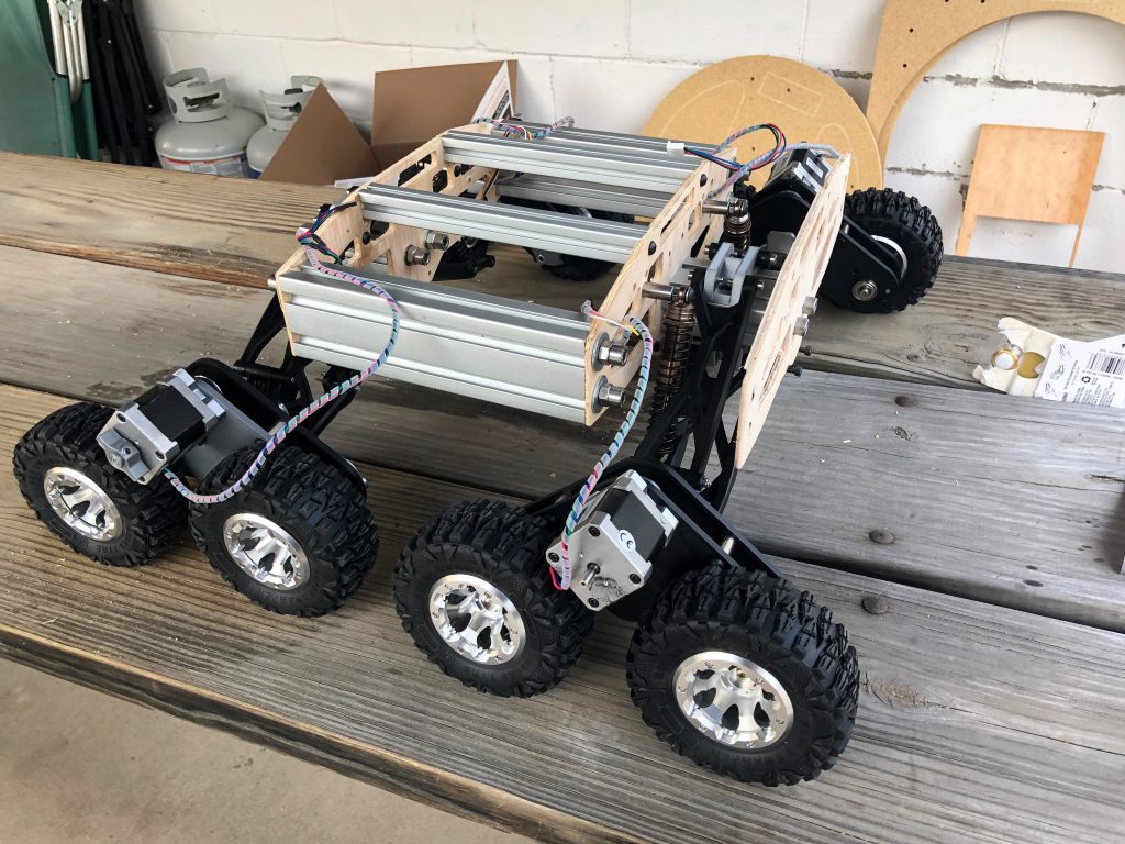
I am very proud of what I’ve made here, but it is not perfect. So I think I am in for some pondering. I need to decide where I go from here. I have some ideas, and I’ll reuse some of my parts here but I think my next post will have things starting to look a lot different.
